


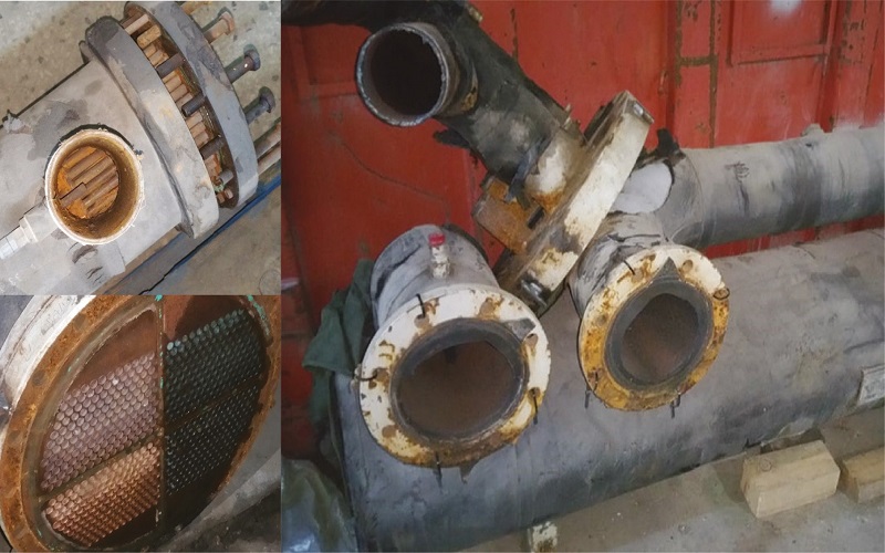
Shell-and-tube replacement with only dimensional data
Contents/ Mục Lục


Comment
Related Post

Heat Recovery From Open Cooling Tower
Heat recovery from cooling towers is a key topic in modern buildings. As the Earth warms, climate change...

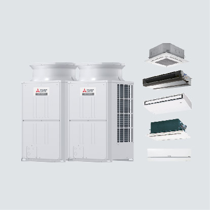
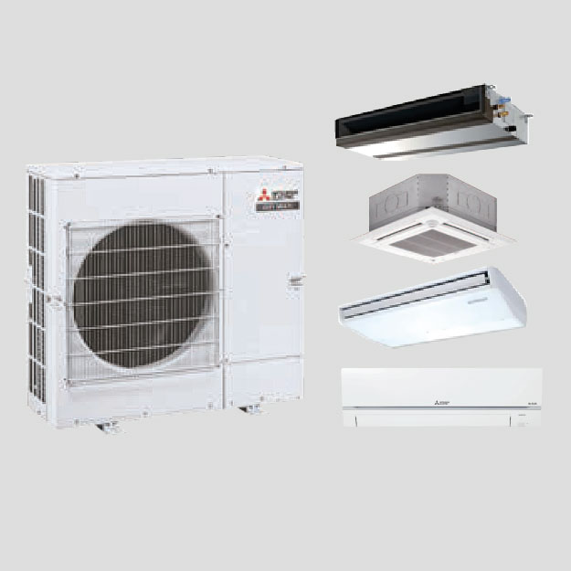
Integrated AHU-DX and CDU-VRF Solution
It is a well-known fact that the world's leading manufacturers of chillers and AHUs primarily originate from the...

Leave a Reply